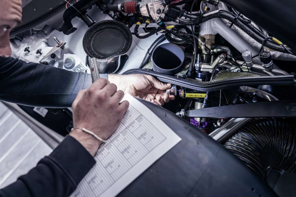
Within our application development process, we craft dynamic driving solutions perfectly tailored to existing vehicle models. For instance, when a new BMW model is introduced to the market, we engineer a compatible chassis. Click “Discover now” to explore the process of our application development.
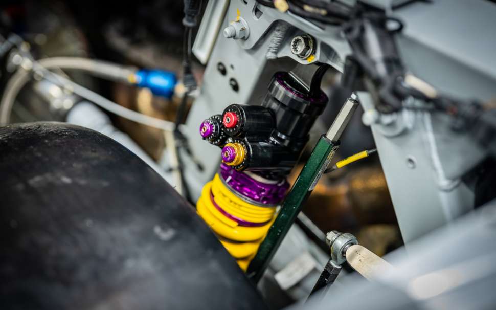
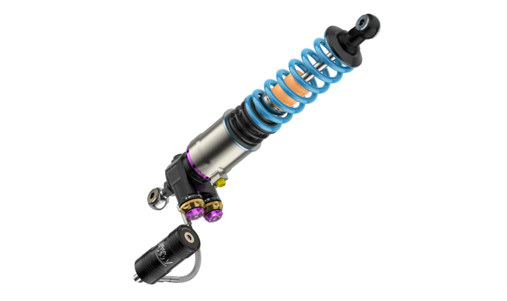
Unlike our application developments, system developments follows a more adaptable process. Customer or internal requirements and preferences regarding our chassis technology are discussed. Then we assess potential optimization avenues. Subsequently, our engineers delve into the pre-development phase, researching chassis-specific solutions. It’s worth noting that numerous projects from the OEM sector traverse through our pre-development and system development departments.
With the DamperTool by KW Suspensions, damper characteristics can be displayed. This enables us to visualize the adjustment range of the damper. In addition, different setups can be simulated and compared. This is particularly helpful when tuning the vehicle on the racetrack, but also on our in-house 4-post and 7-post vehicle dynamics test bench.
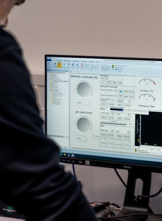
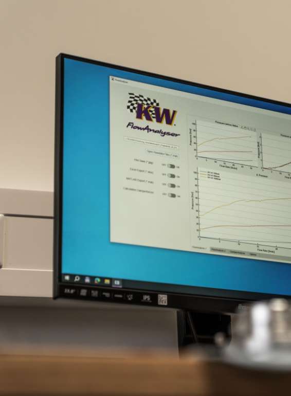


Our headquarters in Fichtenberg is not only a modern production facility for our world-famous KW automotive coilovers. It is also a development and test center for our latest applications and most complex technologies. In addition to simulations at an early stage of development, we also have many specific testing facilities. Here, the performance of the products is validated under laboratory conditions. Durability tests are carried out. So-called performance factors describe the properties of the products, which could not be more different due to KW automotive’s wide range of applications. With the combination of virtual simulations and real component tests, we make our products precisely predictable and calculable. This clearly sets us apart from the competition.
There are a total of 40 developers at our headquarters in Fichtenberg with various specializations. The virtual development methodology supports us from the beginning of a development in the various development stages right through to the finished product. The field of simulations used is now very broad and ranges from FEM/CAD calculations to virtual damper design and vehicle tuning. As a result, our customers and (technology) partners end up with a product that is reliable and robust.
Optimum material distribution by analyzing our products. This allows us to reduce the weight or increase the load-bearing capacity of the product.
We save time efficiently as we can carry out virtual tests without a prototype or vehicle having to be physically present. Our customers also benefit from this.
Due to the time savings, we also reduce the costs incurred.
Design errors are detected early and can be rectified without losses.
Through simulation, we get a precise understanding and accurate results in areas that are not accessible with measuring equipment.
Without the range of simulation tools, we would not be able to save so much in terms of material, time and kilometers. This is a big plus for all players.


To the motorsport references

For reference

For reference
description1
Vorteile für Kunden
Vorteile für Kunden
Mit einem Fahrdynamikprüfstand des BAR-Honda-F1-Teams positionieren wir uns als innovativen Vorreiter und wertvollen Entwicklungspartner innerhalb der Fahrwerksbranche.
Unser erfahrenes Team aus Ingenieuren und Technikern nutzt den Prüfstand, um Fahrwerksparameter (z. B. Aufbauresonanz-Frequenzen, Dämpfungsgrad, Nickverhalten, Aufbaubewegungen, dynamisches Fahrzeugniveau und Radlastschwankungen) gewinnbringend auszuwerten.
Vorteile für Kunden
Tool zur Simulation:
Unser Ziel ist, ein mechanisches Ventil um einen Elektromagnet zu erweitern. Hierfür schicken wir mithilfe einer Spule Strom in das Bauteil. Es entsteht ein Magnetfeld, das Pole ausbildet. Diese Pole ziehen einander an. Mit der Software JMAG erstellen wir einen digitalen Zwilling. Dadurch können wir vorhersagen und verstehen, wie die Energieumwandlung zur Kraft stattfindet.
Wir fügen dem digitalen Modell Daten über das Material, die geografische Lage des Materials und die Art des Bauteils hinzu. Das gibt uns Aufschluss darüber, wie sich das Material beim Durchdringen von Magnetfeldern verhält. Wir machen die Simulation mithilfe physikalischer Gesetze berechenbar.
Zur Prognose findet die sogenannte Diskretion statt. Das große, komplexe Gesamtmodell wird in kleine, weniger komplexe Teilmodelle aufgelöst. Jedes Teilmodell kann individuell berechnet werden und berücksichtigt die Daten der anderen Teilmodelle. Dadurch lokalisieren wir schneller Probleme.
Aus der Summe der Berechnungen bestimmen wir, wie sich die Teilmodelle gegenseitig beeinflussen und auf das Magnetfeld reagieren. Zum Schluss erfolgt das Post-Processing und die Validierung. Wir bereiten unsere Erkenntnisse auf und geben dem Kunden Handlungsvorschläge auf Basis der errechneten Daten.
Um die Durchfluss-Druck-Kurve eines Druckstufen- oder Zugstufenventils anzupassen, messen wir den Druckabfall.
Wir messen die Geräuschbildung (Turbulenz), indem wir mithilfe eines analytischen Ansatzes den Lärm abschätzen, der durch turbulente Strömungen (ungleichmäßige Bewegungen des Fluids) erzeugt wird.
Die Messung des Unterdrucks (Kavitation) simuliert Dampfblasen innerhalb einer Flüssigkeit in Niederdruckbereichen. Diese treten an Orten auf, an denen die Flüssigkeit auf hohe Geschwindigkeiten beschleunigt wurde.
The flow test bench can be used to test and optimize valves before they are installed in the damper. This is not a virtual simulation, but a real measurement setup. This allows us to analyze valves without interference from other components and properties such as gas pressure, friction or leakage.
We start by clamping a valve in the test bench. A pump is used to pump hydraulic oil (identical to our performance oils in the shock absorbers) through the valve. The oil flows through the valve at a predefined flow rate. The resistance caused by the valve results in a pressure drop. The difference in pressure before and after the valve is the damping force that is relevant for us. Important: The hydraulic oil runs through the valve with a linearly increasing volume flow of 0 l to 40 l per minute (max. 130 bar). The continuous gradient shows how the pressure drop changes. With this tool we try to understand the complexity of the valves. It also allows us to set the ideal parameters and find out our application possibilities.
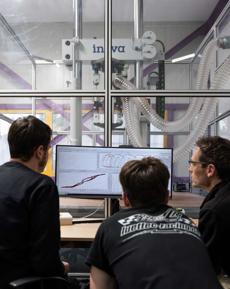
During development, we carry out objective and subjective assessments. In the objective assessment, we use data logging to get an idea of the driving test. his means that we not only work objectively with the help of measurement data from our 7-post rig, but also carry out test drives on the streets and racetracks.
Thanks to our application developments, we already have a great deal of experience in subjective assessment. This results from the expertise of our employees from the workshop, system development, application development, technical support, springs, wheel/adapter systems, project management and many other positions. In addition, we have accompanied many OE projects in the several decades in which we have been practicing. Here, too, we have always attached great importance to our driving impressions. We are therefore able to support projects based on data as well as real test drives and driver feedback.
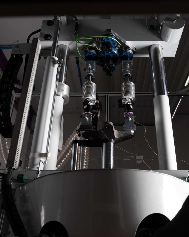
To ensure that we have developed the ideal damper setup, we carry out long-term tests under laboratory conditions that can be reproduced at any time. This ensures that the final characteristic curves and damper properties are still good even after extreme use (e.g. 24-hour races or an average vehicle life) and that there are no failures. We use two servo-hydraulic test systems for testing. The characteristics of the systems differ depending on their future purpose.
For road applications, we use a test system from Schenk. Here, up to four test specimens can be tested simultaneously. The hydraulic cylinder used achieves a speed of up to 1.75 m/s with a nominal force of 40 kilonewtons. Requirements from the off-road sector and other fields of application in the area of energy absorption require significantly greater assurance of product properties. This is where KW automotive relies on a special test bench from Inova. Achievable speeds are over 7 m/s and a maximum stroke of 300 mm (nominal force at 100 kilonewtons). To achieve these values, a specific hydraulic cylinder, a high-performance pump unit and pressure accumulator units are required. The entire power pack delivers up to 1,200 liters of hydraulic oil per minute during peak excitation. The power consumption of the motor is over 120 kW. In addition, we use the systems not only for continuous operation, but also to evaluate the acoustics and noise analysis of our products. Thanks to these extensive tests, our customers benefit from products with maximum reliability.
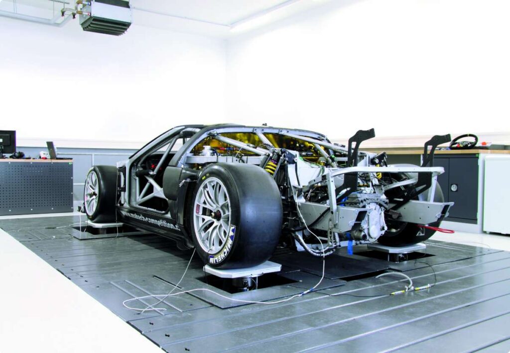
Our vehicle dynamics test bench from the BAR-Honda F1 team has been part of the KW automotive headquarters in Fichtenberg since 2008. With this, the managing directors Klaus and Jürgen Wohlfarth have positioned themselves as innovative pioneers and valuable development partners within the suspension industry.
Since then, a team of engineers and technicians has established within the company, which profitably evaluates a wide range of parameters such as body resonance frequencies, damping level, pitching behavior, body movement, dynamic vehicle level and wheel load fluctuations.
Our vehicle dynamics test bench now offers great added value to numerous successful and internationally active motorsport teams and car manufacturers. We are closely involved in optimizing the suspension solutions of our valued customers and partners. In this way, we maintain the spirit of innovation in the chassis industry and actively contribute to it on a daily basis.
With our virtual 4-post, we use specific vehicle data and the desired driving characteristics to determine the appropriate spring rate and the corresponding damping characteristics for a vehicle.
With the virtual 4-post, we can adapt our dampers to the desired target values even before production. We can export the final characteristic curves from the software. This enables us to coordinate with our customers or to compare the simulated values with the real values measured on the damper test bench. Existing damping characteristics can also be imported and simulated.
The flow test bench can be used to test and optimize valves before they are installed in the damper. This is not a virtual simulation, but a real measurement setup. his allows us to analyze valves without interference from other components and properties such as gas pressure, friction or leakage.
We test the component strength as part of the flow simulation. This allows us to validate whether the damper is resilient enough before production. If the requirements are not sufficient, the simulation can be used to determine exactly which component needs to be reworked.
We also carry out topology applications. This is a process for optimizing shapes using algorithmic models. Based on our predefined specifications for load, condition and restriction, we can use the process to determine the best possible material layout, for example for our wheel spacers.
We test the reliability of our products during fatigue strength testing. Fatigue failure analysis helps us to identify sources of error and thus prevent product malfunctions. This enables us to optimize our designs in terms of reliability and performance.
Ansys is a software for strength and flow simulations. It is considered the state-of-the-art framework on the current market. With the Ansys simulation tool, our engineers are able to close the gap between design and reality. This makes it possible to see how a product will perform under a wide range of influences even before it goes into production.
This virtual simulation is used to test the magnetic, electrical and mechanical properties of an electromagnetic assembly. This is then transferred to a simplified CAD model. The starting point for the simulation of electromagnetic valves is the desire to add an electromagnet to a mechanical valve. To do this, electricity is sent into the component using a coil. This creates a magnetic field that forms poles. These poles attract each other. In order to understand and predict how the energy conversion to force takes place, a digital twin of the component is created in the JMAG simulation software.
Data (material data, geographical location of the material, type of component) is added to the digital model. This should ultimately provide information on how the material behaves when penetrated by magnetic fields. We use physical laws and equations to make the simulation calculable.
Discretization is used to find solutions and predict parameters. Here, the large, complex overall model is broken down into many small, less complex sub-models. Each small sub-model can be calculated individually and simultaneously takes into account the data of the other sub-models. This makes it much easier and quicker to localize any problems that may arise.
From the sum of the calculation of these many individual sub-models, we can ultimately determine exactly how these models influence each other and how they react to the magnetic field. The sub-models are put together and a solution is formed. Finally, post-processing and validation takes place. This is where the engineers prepare the data and provide the customer with suggestions for action based on the calculated data.
The term “CFD” means Computational Fluid Dynamics. Here, numerical methods are used for the approximate solution of fluid mechanical problems. This allows technical processes within a component to be investigated and visualized.
The measurement of the pressure drop is used to adjust the flow-pressure curve of a compression or rebound valve. When measuring turbulence, an analytical approach is used to estimate the noise generated by turbulent flows.
The measurement of negative pressure (cavitation) simulates vapor bubbles within a liquid in low-pressure areas. These occur in places where the liquid has been accelerated to high velocities.
The term “CFD” means Computational Fluid Dynamics. Here, numerical methods are used for the approximate solution of fluid mechanical problems. This allows technical processes within a component to be investigated and visualized.
Marken | Heading #2 | Heading #3 |
|---|---|---|
 | Simple content | Simple content |
Contact us on our social media accounts like Facebook or Instagram.
Kontaktiere uns einfach und bequem über unsere Social Media Kanäle.
Auf unseren Markenseiten findest du den Chat zu deinem Ansprechpartner.
KW automotive GmbH
Aspachweg 14
D-74427 Fichtenberg
Telefon:+49 (0) 7971 9630-0
Telefax:+49 (0) 7971 9630-191
E-Mail: info@kwautomotive.de
Vertretungsberechtigte Geschäftsführer:
Klaus Wohlfarth, Jürgen Wohlfarth
Registergericht:
Amtsgericht Stuttgart
Registernummer:
HRB 571255
Umsatzsteuer-Identifikationsnummer
gemäß § 27 a Umsatzsteuergesetz: DE 812 382 653
Verbraucherinformation gemäß Verordnung (EU) Nr. 524/2013:
Nachfolgend finden Sie den Link zur OS-Plattform der EU-Kommission: https://ec.europa.eu/consumers/odr/.
Unsere E-Mailadresse lautet: info@kwautomotive.de.
Streitbeilegungsverfahren:
Wir nehmen nicht an einem Streitbeilegungsverfahren vor einer Verbraucherschlichtungsstelle teil. https://ec.europa.eu/consumers/odr/.